Bond Failure Analysis in Engine and Suspension Mounts
Bond Failure Analysis in Engine and Suspension Mounts
Why are Engine Mounts and Suspension Mounts Important?
The underbody of your vehicle contains some of the most engineered components in the vehicle system. The engine and suspension mounts may not look sexy, but they are a key integral part in vehicle development. Properly engineered mounting systems are paramount in safety, noise and vibration isolation (NVH) and prevention of high dollar warranty claims. Understanding the forces that dictate design and construction material selection is necessary to properly engineer and manufacture these components. They are required to withstand high dynamic loading in multiple directions and dampen vibration to the rest of the body frame.
Engine and suspension mounts typically will be comprised of three components: An inner metal, outer metal, and isolation rubber. The inner metal is typically a drawn or cast “tube” with is the bolt location for the engine or suspension assembly. The outer metal is typically a lighter gage metal of cut tube that is press fit into the frame component. The rubber component is the interface between the two metals that provides the isolation and damping characteristics of the mount. The metals utilized are typically carbon steel, however cast aluminum metals are currently being utilized as well.
Bond Failure and Rubber Strength
Each interface in this system must be built to withstand high dynamic loading, especially in the sheer direction (axial). The carbon steels utilized are inherently not a problem in loading, however the rubber strength and bonding of the rubber to the metals are typically the problem in failure assessment. Essentially we are “gluing” the rubber to the metals. This “glue” and molding operation must result in a component that can withstand tens of thousands of pound force over the lifetime of the component. The manufacturers of these components will validate the process and components by performing push out tests for ultimate loading assessment, as well as dynamic cycle loading to validate durability. The acceptable failure mode for push out testing is 100% rubber tearing above the defined upper load limit. Any indication of failure occurring at the metal to rubber interfaces is considered suspect and warrants causal analysis to identify the problematic interface.
How to Assess Failure Mode
Although the three structural components of the mount are obvious to the eye, several other key structural components exist that must be understood to properly assess the failure mode. The metals utilized must be prepared such that an adhesive can be applied and not delaminate under the shear conditions. The metals are prepared after forming with a process called phosphating (or phosphatizing). In this process the metals are immersed in a highly acidic bath of zinc and calcium phosphate. An etching process occurs at the metal surface which then allows for a nucleation site for crystal growth. The nucleation and growth rates are controlled by the bath chemistry and immersion time. buy celexa online no prescription
Although many different types of phosphating exist, the calcium modified zinc phosphate chemistry has long been identified as the most desirable chemistry for rubber to metal bonding, resulting in a microcrystalline “spherical” type crystal called Scholzite. The crystal is highly hydrated and is inherently not brittle like it’s macro-crystalline cousins. This crystalline layer is not only a good structural bonding surface, it also provides good corrosion resistance for the unbonded portions of the metals.
Proper Application of Adhesives
After the metals are prepared, the adhesive system is applied. The overwhelming majority of adhesives in this application are manufactured by Lord Chemical and go by the brand name Chemlok followed by a product number. Lord manufactures adhesives with both water and organic solvent base, and are applied with roll coating, spray, or dip and spin. Several of the adhesive systems are also two part (a primer and a top coat). The adhesives undergo a light heat pre-bake which will not result in a cure condition but leaves the metals dry to touch and not tacky prior to molding. Careful consideration has to be made for the dry film thickness and uniformity in application.
Once the adhesives are applied to the metals, they are assembled into the rubber mold. Rubber compound is injected into mold and heat applied to the mold that is sufficient to vulcanize the rubber as well as activate the curing process of the adhesives. It must be noted as well that the rubber compound is also multi-component in that it will contain inorganic fillers, carbon black, vulcanizing chemistry, lubricants, and antioxidants, which can give rise to problems in the rubber integrity itself if not properly formulated or controlled. When the component is cooled, it is then ejected from the mold and ready for testing or assembly. buy desyrel online no prescription
Bond Failure Analysis: A Closer Look
After understanding the chemistry and processes that go into manufacture of the mount component, only then can be adequately assess the data generated from comprehensive failure analysis when they occur. One such failure analysis was recently undertaken which utilized a systematic analytical approach at each interface examined to understand the ultimate root cause, which was over-application of the primer coating and localized overheating of the primer layer of the adhesive system.
A bushing was received with a rubber to metal bond failure at the insert interface. The adhesive coating system was described by the client as Lord Chemlok xxx primer (with 0.2-0.5mil nominal film build specification), and Lord Chemlok xxxx (with 0.7-1.0mil nominal film build specification). Examination of the insert showed a mixed mode failure, partially due to rubber tear and two isolated areas that presented as failure to insert substrate. Examination of the location of the two areas that showed failure to substrate corresponded to the locations where rubber enters the mold through the sprue locations. Additionally, these areas correspond to areas where the rubber density in the bushing is highest. The intact outer material was sectioned longitudinally to expose the rubber back for examination. It must be noted that the rubber back surfaces were much harder and much less pliable than the bulk rubber material (by tactile response only).
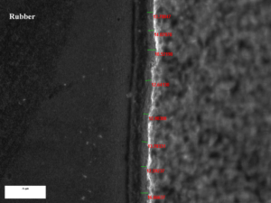
An area of intact rubber at the insert surface was extracted to examine adhesive film build. A transverse section was cut, impregnated with epoxy to fix the rubber, mounted, polished, and examined by optical microscopy in representative areas. Measurements were performed of the primer and top coat adhesive layers through the section. The results of this analysis are provided in table 1 below and the image provided in figure 8. The analysis indicates that the primer film exceeds the application guidelines, and the top coat adhesive is on the high side of the application guidelines.
Designation Layers Min. Thickness Max. Thickness Average
Bushing 2 Primer coat 12.59 μm (0.5mils) 18.52 μm (0.7mils) 14.37 μm (0.6mils)
Adhesive 23.70 μm (0.9mils) 28.15 μm (1.1mils) 25.75 μm (1.0mils)
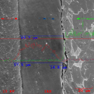
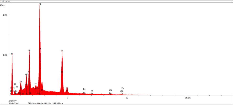
The prepared metallographic specimen was subsequently sputter coated with gold to enhance surface conductivity and imaging and submitted for line profile analysis using techniques of SEM (Scanning Electron Microscopy) and EDS (Energy Dispersive X-ray Spectroscopy). The adhesive interface was imaged at 1000X magnification and elemental concentration of chlorine (a common prime constituent of both the top coat adhesive and the primer adhesive), titanium (an exclusive constituent of the primer only), and iron (substrate constituent). The resulting analysis indicates a homogeneous primer distribution of 14.8 microns (0.6mils), a total film of 49.7 microns (2.0mils), and penetration of top coat adhesive into the rubber system at a depth of 7.8 microns (0.3mils).
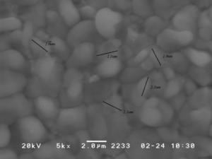
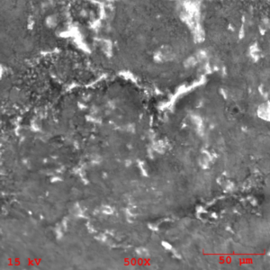
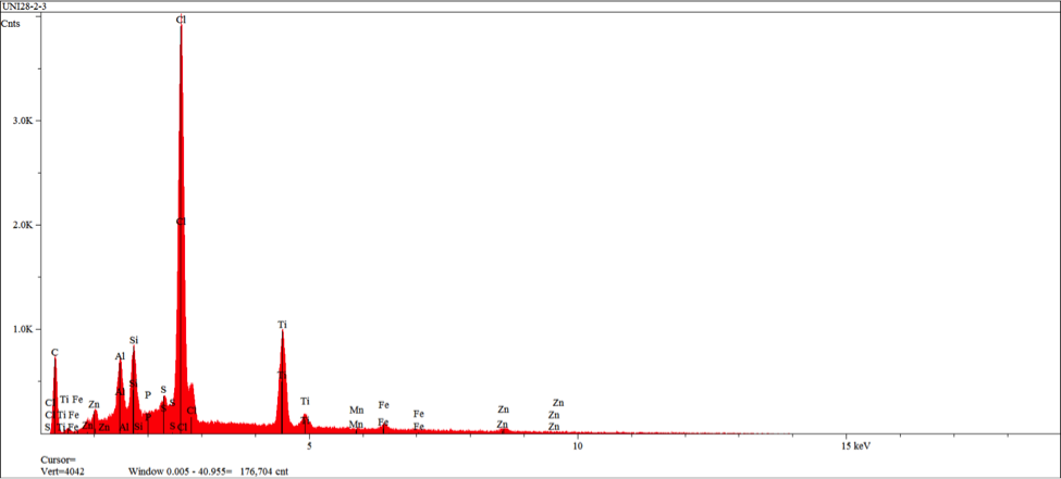
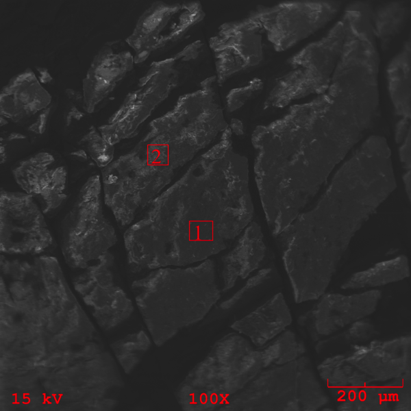
The zero degree location on the insert was examined by SEM (Scanning Electron Microscopy), and EDS (Energy Dispersive X-ray Spectroscopy) for semi-quantitative identification of elements with atomic number greater than five. The resulting SEM images obtained indicate morphology associated with residual adhesive material over a microcrystalline calcium zinc phosphate conversion coat (see figures 10-11). EDS analysis was performed at the three areas shown in figure 11 (see figures 12-14). EDS analysis in areas 1 and 2 indicates the presence of calcium modified zinc phosphate conversion coating elements with minor residual primer elements. EDS analysis in this area indicates elements associated with the primer adhesive.

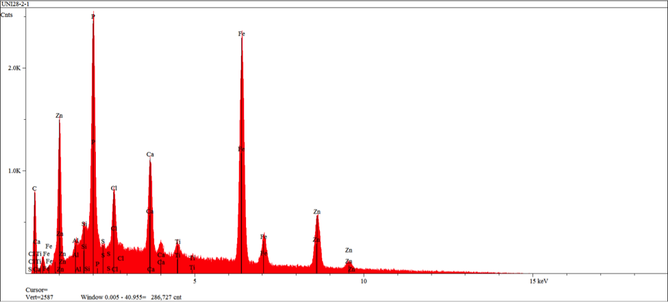

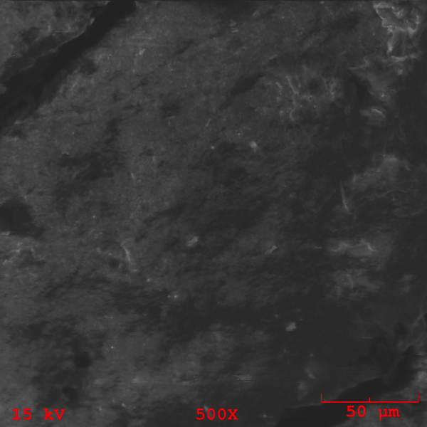
The areas of mating rubber back were isolated from the bulk specimen and mounted on a SEM mount for analysis. The resulting SEM images (figures 15-16) indicate unremarkable morphology associated with an amorphous deposition of an adhesive. buy effexor online no prescription
It is important to note the cracking of the deposition seen in figure 16 as it indicates embittlement of the coating realative to the underlying rubber. EDS analysis of the rubber back surface (figures 17-18) indicate elements associated with the Chemlok XXX primer exclusively.

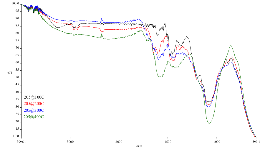
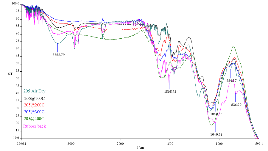
The rubber back in the failed region was analyzed using a microscopic FTIR (Fourier Transform Infrared Spectroscopy) with an ATR objective. In addition, the cured exemplar Chemlok xxx samples were analyzed using the sample technique. The overlay FTIR spectra are supplied as figures 20 and 21. The results of the FTIR analysis of the cure samples indicate consumption of organic functionaity as the temperature increases, particularly noteable in the hydroxyl region (3270cm-1) and the band at 885 cm-1. Comparison of the rubber back sample to the cure samples indicate full consumption of the 885 cm-1 characteristic of the cure samples at 200C and beyond. Although hydroxyl consumption is not realized in the rubber back sample, there is a shift in this band and additional extraneous functionality present characteristic of a nitrogen containing organic which would account for the differential shaping of the hydroxyl region.
Rubber to Metal Bond Failure--What went Wrong?
At two localized areas, the rubber to metal bond failure exhibited failure to insert substrate. Examination of the film build in an intact area indicates over application of the primer adhesive and high side application of the top coat adhesive. SEM and EDS examination of the insert substrate in the failure region indicates intact presence of a microcrystalline calcium modified zinc phosphate conversion coating with scattered primer adhesive remnants. SEM and EDS examination of the mating rubber back indicates the presence of primer adhesive exclusively. The failure mode in this region was demonstrated at the primer and conversion coating interface.
Discoloration of the primer adhesive present at the rubber back matches discoloration of an exemplar cure at excessive heat of 200 deg C (392 deg F). Lord technical data sheets for Chemlok xxx describe an upper temperature limit of 300 deg F for this material. FTIR analysis of this surface confirms the exposure to excessive heating conditions.
Based on the provided analysis, the physical cause for failure at the localized region interface is due to excessive heating of the localized region. Although there is evidence to suggest that the rubber and top coat in this region also were subjected to excessive thermal effects, the interface failure occurred at the interface most susceptible to embrittlement effects, and that is at the primer bond plane where excessive application of the primer adhesive is present.
Written by Lloyd Kaufman
Director of Materials Sciences
RTI Laboratories, Inc.